System support: Windows XP & Windows 7 & Windows 10
Supported versions of MATLAB: EcoCoder supports MATLAB2010b and above
MATLAB component requirements: ①MATLAB, ②Simulink, ③Real Time Workshop, ④ Realtime Workshop Embedded Coder,
⑤ Stateflow, ⑥ Stateflow Coder
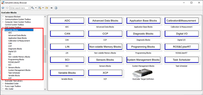
- Run the EcoCoder installation, which automatically adds all EcoCoder’s library blocks and S-functions to Simulink;
- Capture all the hardware driver software with EcoCoder S-functions, including ADC drivers, CAN drivers, digital 10 drivers, PWM drivers and etc. And capture the real time operating systems with EcoCoder task scheduler S-function;
- Link the application software, aka and Simulink blocks to the hardware driver software via EcoCoder library blocks and S-functions in Simulink environment;
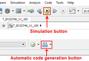
- Run simulation in Simulink to verify models and software integrity;
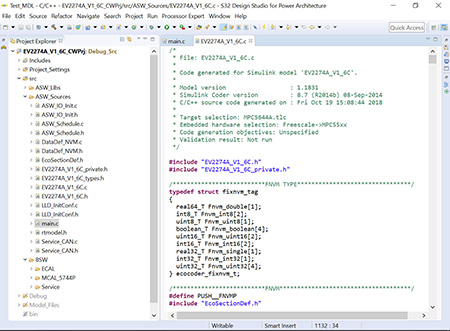
- Define the signal properties and parameter properties in Simulink, which will be output for the generated A2L file;
- Click “code generation” button, EcoCoder will generate the microprocessor compatible codes;
- Click “compile” button, this will invoke the compiling and linking process, running in the background, which will run the compiler, like CodeWarrior, to compile the application code and hardware driver code together and generate the executable codes.
- Machine executable file, for example MOT file for Freescale MPC56xx, 57xx series microprocessors;
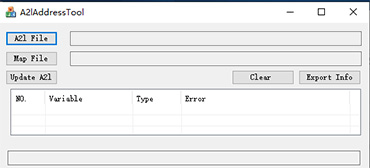
- A2l file, which a descriptive file contain all necessary info for the calibration tool to interpret the Controller protocols;
- CAL file, containing only calibration data, not the code.
EcoCoder has various library blocks and S-Function modules: System initialization setting module (ECU_Settings), ADC analog signal processing module (ADC), CAN bus data processing module (CAN),Task scheduling module (Task_Schedeuler), IO driver module (Digital IN/OUT).
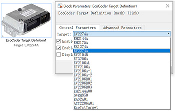
Under the ‘General Parameters’tab,this block defines the specific model of Ecotrons VCU hard ware that you are using.Place this block in application model, usually at the top level, to select the VCU model for users’ application.
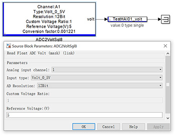
ADC is used for collecting the input analog voltage.
This mode is used for measuring the digital 10 input and controlling switching output. It includes the switch mode and PWM mode.
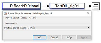
Digital IN
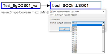
Digital OUT
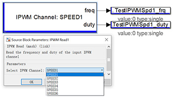
IPWM
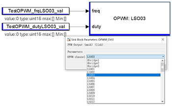
OPWM
Function: Read CAN message, Send CAN message, Data analysis.
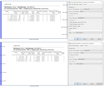
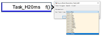
There are two tasks for the task scheduler: high-priority task and low priority task.

Besides, it also can monitor the task load rate. If the task execution time is too long and the load rate is too high, the application layer software the calculation module will need to be adjusted.
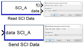
SCI module includes SCl_RxData and SCI_ TxData, which can read and send SCI data for selected channel.
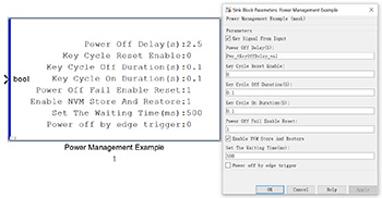
System Management Blocks module includes power management, power down and system free running counter time reading functions.
Diagnostic Blocks are designed to meet users OBD requirements and UDS diagnostic requirements, including HardWare_DTC, PwrStgDTCGetBit and SoftWareCoreCheck_DTC.

Document


