


Introduction
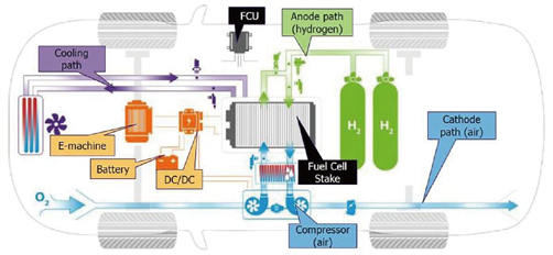
Fuel Cell Engine (FCE) is a complex, multidisciplinary system, as the control unit for FCEs, FCU needs to have strong computing and processing capabilities and rich collections of I/O to effectively manage and coordinate various of subsystems, to ensure the safe and strong power generation from the battery system for prolonged period of time.
Features:
-Based on the automotive grade 32-bit MCU Infineon AURIX™ series TC27xT platform, with multi-core architecture.

-The design and development of software, hardware, and control strategy comply with ISO26262 functional safety requirements. With a built-in safety monitoring chip, our FCU is ASIL-D rated.
-Built-in basic software (BSW) supports automatic code generation tool EcoCoder (rapid prototyping), and all popular input/output of a typical fuel cell system. BSW is packaged in the MATLAB/Simulink environment, and users can develop control strategies with 100% model-based design methods.
-Equipped with a CAN bus-based software flashing tool, which is guided by the bootloader flashed into the microcontroller in advance.
-Gas path management: Precise control of the hydrogen flow, airflow, pressure, humidity, and temperature required by the fuel cell system.
-Water and heat management: Precise control and adjustment of the circulation, heating, heat dissipation, air temperature, cooling water temperature to improve the power efficiency and reliability of the fuel cell system.
-Electrical management: Monitoring the battery pile voltage and current, adjust the output power, and control the fuel voltage within a reasonable range, manage the residual power, and provide the voltage and current protection.
-Data communication: Communicating with other subsystems, interchange important data and control signals.
-Fault diagnosis: Capable of perform fault diagnosis, raise warning, and initiate protection routine for various subsystems.
| Functions |
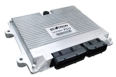
EF2275B01 |
| Main chip |
Infineon TC275T: 200MHz, Flash 4M, SRAM 472K, Float Point Capability |
| Monitor chip | (SBC)TLF35584QVVS2 |
| Supply voltage | DC 12V/24V (9-32V) |
| Peak voltage | DC 36V |
| Reprogramming | Bootloader, CCP protocols |
| CAN Bus | 4 channels 2.0B |
| LIN Bus | 1 channel |
| EEPROM | 64K |
| Sensor supply output | 9 channels, 5V |
| Analog Input | 28 channels |
| Digital Input | 8 channels, 4 channels high effective, 4 channels low effective |
| PWM input | 6 channels, Hall type input |
| Frequency signal input | 6 channels |
| Low-side driver | 22 channels; 6 channels, 1.5/2A; 9 channels, 0.8/1A; 7 channels, 0.16/0.2A; 10 channels can be multiplexed as PWM output |
| High-side driver | 9 channels; 4 channels, 1.5/2A; 5 channels, 0.4/0.5A; 5 channels of which can be multiplexed as PWM output |
| Peak and Hold | 4 channels, Peak maximum current 7A |
| H bridge | 2 channels, 3A/8A |
| Operating temperature | -40 ~ +110℃ |
| Storage Temperature | -45 ~ +125℃ |
| Working humidity | Satisfying 0 ~ 95%, noncondensing |
| Protection category | IP67 |
| Pin number | 121 Pin |
| Dimensions | 250mm×194mm×37mm |
| Housing Material | Die-casting aluminum |
| Weight | ≤700g |
| Mechanical characteristics | Vibration, shock, drop test done as in ISO16750 |